- Home
-
Shop Now
- Fuser & Maintenance Kit
- PC / Logic Board
- Hard Drive/Mass Storage
- External Panel & Cover
- Paper Tray
- Paper Path Part
- Internal Part & Component
- Printer - Whole Unit
- Toner & Ink
- Network Interface
- Accessory
- Flatbed Scanner & ADF Assembly
- Image Transfer
- DesignJet/Plotter Part
- OfficeJet Pro
- Computer/Laptop Parts
- Technical Resources
- Contact Us
- Blog
- Laser Pros International | Laser Printer Parts
- >Blog
- >Replacing CF367-67907-3 Transfer Roller
Replacing CF367-67907-3 Transfer Roller

Author: Renee Roberts, Marketing Assistant
Published on March 13th, 2020
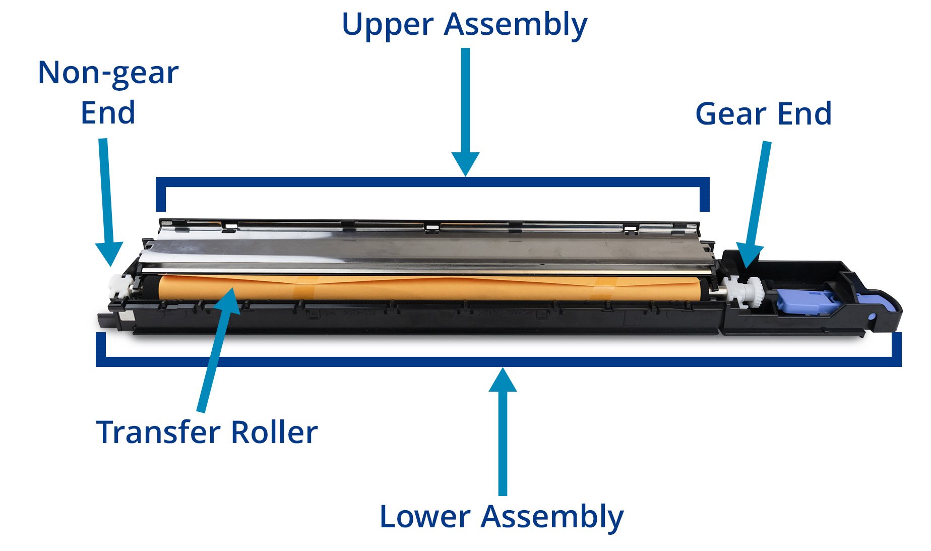
This article explains the process of replacing the transfer roller within the CF367-67907 transfer roller assembly for the HP LaserJet Enterprise M806 and HP LaserJet Enterprise Flow MFP M830. Refer to the diagram below for terminology used in the article.
Transfer Roller Assembly Diagram
Materials/Tools:
- Small flat-blade screwdriver
- A CF367-67907 transfer roller assembly removed from printer
- A new CF367-67907-3 Transfer Roller
Section One: Removing CF367-67907 Assembly from Printer
Follow the steps below to remove the assembly from the printer.
Source: https://support.hp.com/my-en/document/c04193506
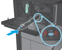
- Open the front door.
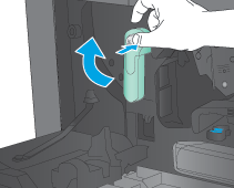
- Rotate the cartridge-release lever down until it clicks into place.
- Press the blue tab, and then slowly pull the transfer roller assembly toward the front of the product until it stops.
- Lift the assembly up to release the catch on the underside, and then remove the assembly.
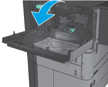
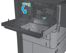
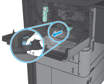
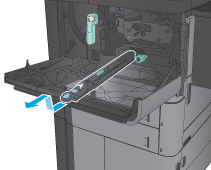
Section Two: Replacing Transfer Roller:
Step one:
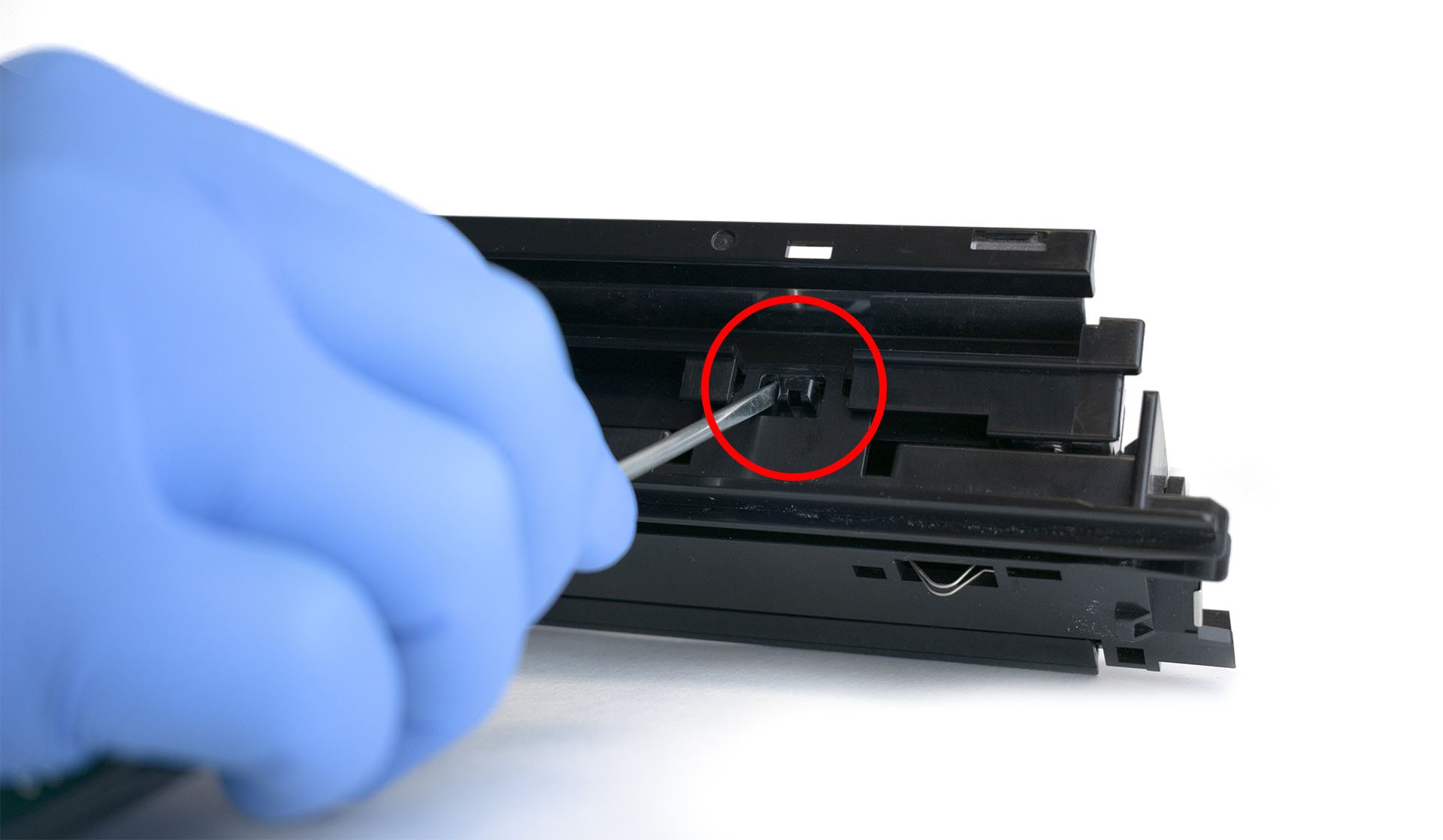
- Locate two tabs identified on the image below:
- Carefully pry and release the two tabs by using a small flat-blade screwdriver.
- Once both tabs are released, the assembly should appear like image below:


Step Two:
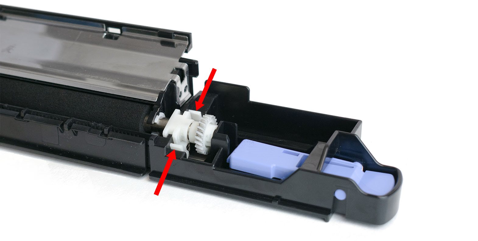
- Locate the gear end of the transfer roller (See diagram at beginning for assistance).
- Press the two tabs located on the bushing to release the gear end of the transfer roller.
Step Three:
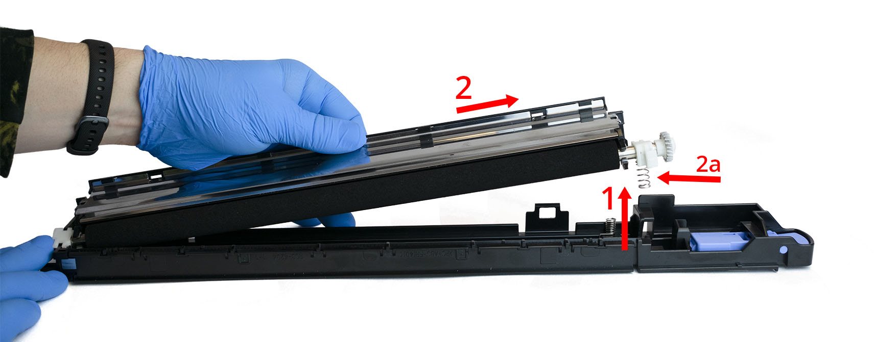
- Lift up, raising the gear end of the transfer roller.
- Once raised, move the upper assembly of the transfer roller assembly to the right (as shown below) and detach from the lower assembly.
- NOTE: The spring under the bushing is not captive and may fall off during disassembly.
Step Four:
- Remove gear, bushing, and spring from the gear end of the transfer roller.
- NOTE: The spring will be reused during assembly.

Step Five:
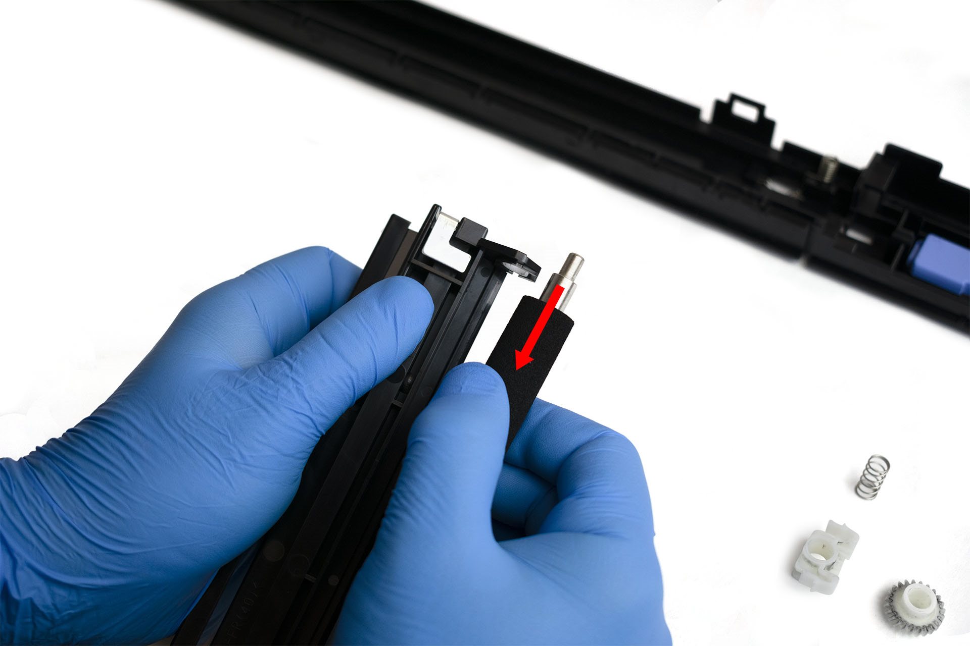
- Locate the non-gear end of the transfer roller (See diagram at beginning for assistance).
- Hold the upper assembly and gently pull the transfer roller down until the shoulder clears the white retainer bushing. Remove old transfer roller.
Step Six:
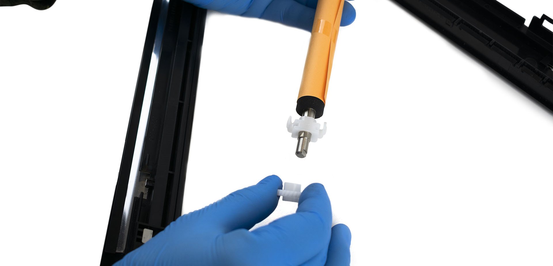
- Locate the new transfer roller, leaving the protective paper intact.
- Remove the gear and bushing from the new transfer roller and set these aside.
Step Seven:
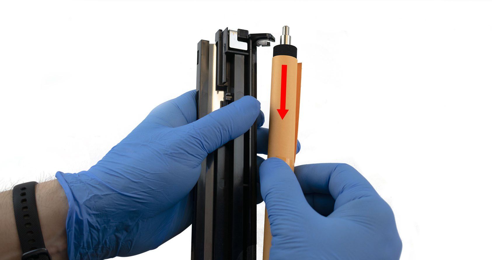
- Insert the gear end of the new transfer roller first, into the upper assembly of the transfer roller assembly.
- Gently pull down the roller until the shoulder clears the white retainer bushing.
Step Eight:
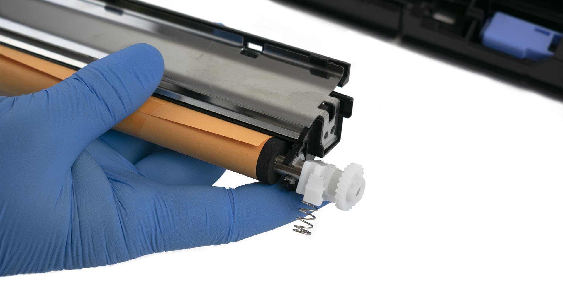
- Install the bushing, gear, and spring onto the gear end of the roller, as shown below:
Step Nine:
- Insert/install the non-gear end into the lower assembly of the transfer roller assembly.
- Press down on the gear end until the bushing locks into place.

Step Ten:
- Press gently down on the upper assembly until the 2 tabs lock back into place.

Step Eleven:
- Remove the orange paper protecting the roller and install the transfer assembly into the printer.

Section Three: Installing CF367-67907 into Printer:
Follow the steps below to reinstall the assembly back into the printer.
Source: https://support.hp.com/my-en/document/c04193506
- Slide the replacement transfer roller into the product until it snaps into place.
- Grasp the cartridge-release button, press the gray button on the lever, and then rotate the lever clockwise until it is parallel to the ground and clicks into place. NOTE: The handle will not rotate unless the button is pressed in.
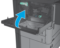
- Close the front door. The front door will not close if the cartridge-release lever is in the unlocked position.
- Do the following:
- Plug in the power cord.
- Turn on the product.
